Search
Mechanical and Fluid Systems
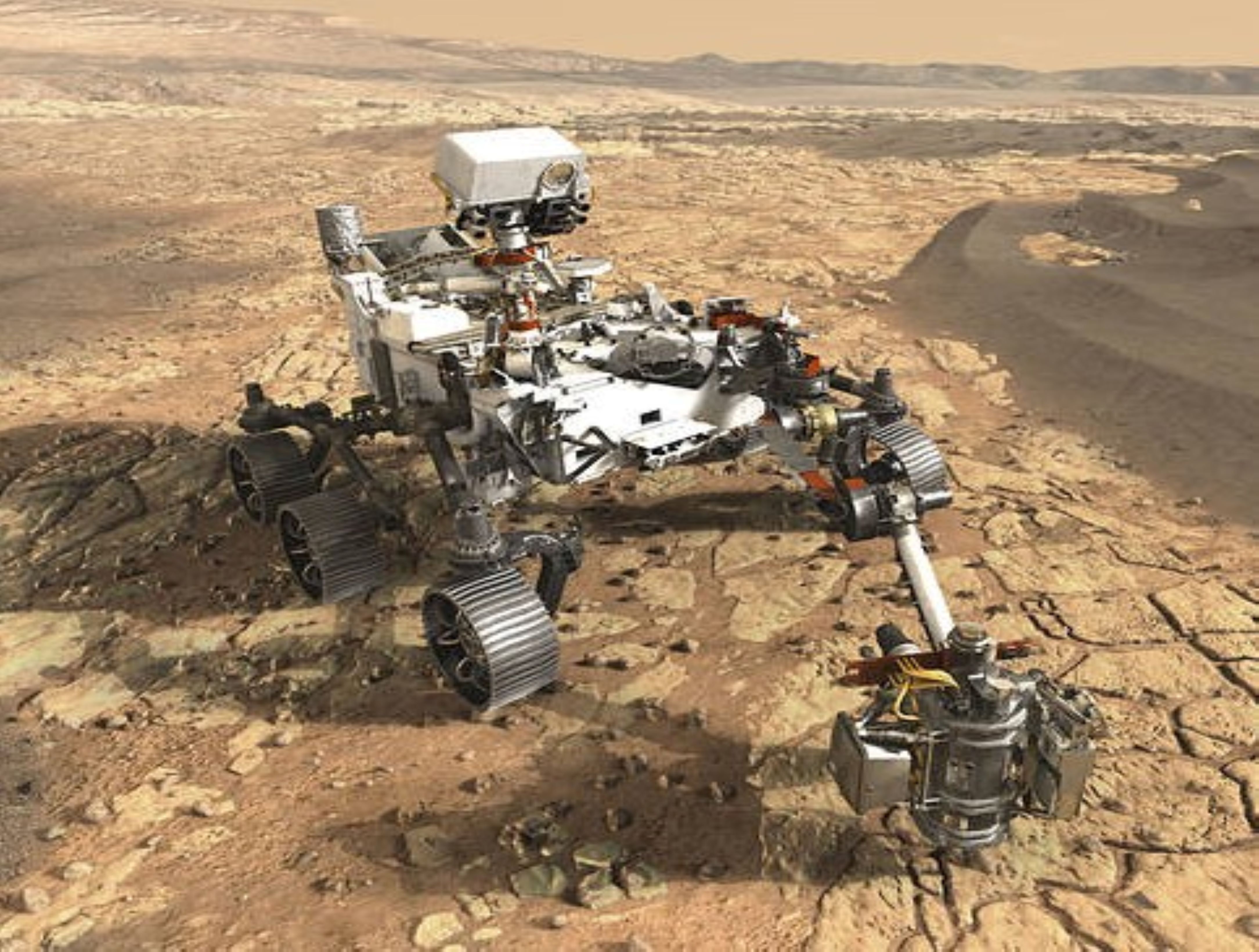
Multi-Link Spherical Joint
The Multi-Link Spherical Joint developed at NASA Johnson Space Center provides a substantial improvement over typical joints in which only two linearly actuated links move independently from one another. It was determined that the rotation point of a trussed link needed to be collocated at a shared point in space for maximum articulation. If not allowed separate rotation, the line of action through a universal joint and hinge acts effectively as another linkage. This leads to a much more complex and uncontrollable structure, especially when considering multiple dimensions.
Comprising the Multi-Link Spherical Joint, a spherical shell encases the cupped ends of each six possible attachments and allows each of those attachments to be independently controlled and rotated without inhibiting the motion of the others. To do this, each link is precisely limited to 15 degrees of rotation off the link centerline, thus allowing a total of 30 degrees of rotation for each link. The shell-and-cup structure can handle the loads of linear actuators that may be used to control and vary the geometry of a truss system utilizing the new joint technology. The calculated operating load that the truss system must handle can be used to scale the size of the joint, further allowing customization of any potential truss system. Additionally, the incorporated linear actuators can be controlled and powered by wiring routed through the joint without putting undo stress on the wires during operation. Accordingly, this innovative joint technology enables more efficient deployment and precise operation of articulating structures.
The Multi-Link Spherical Joint is at technology readiness level (TRL) 4 (component and/or breadboard validation in laboratory environment) and is available for patent licensing. Please note that NASA does not manufacture products itself for commercial sale.
Robotics Automation and Control
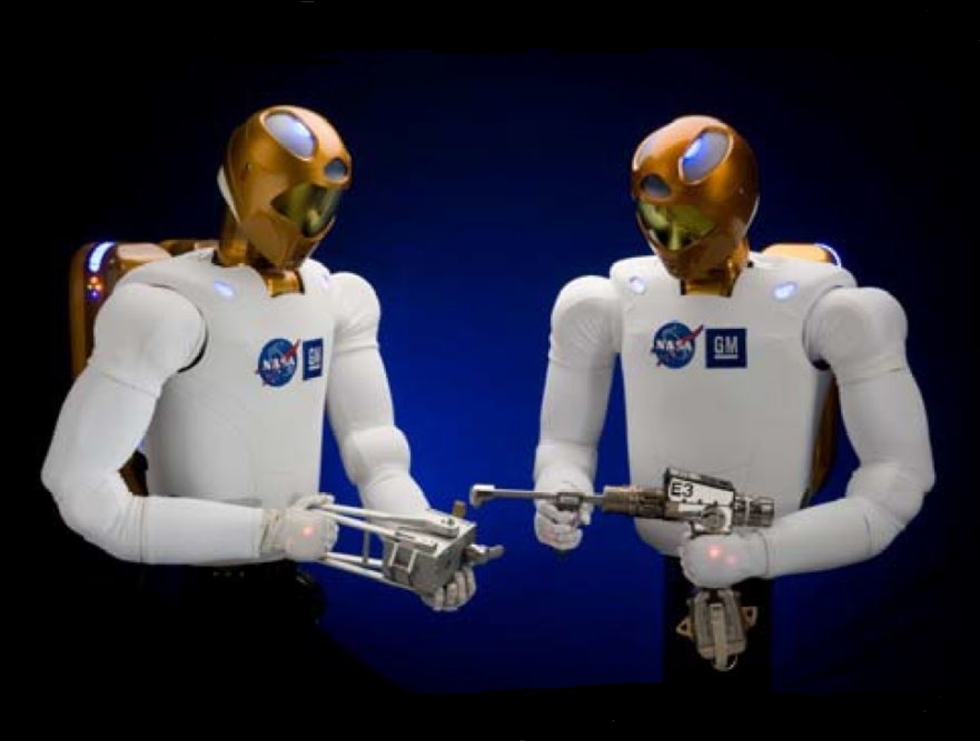
Advanced Humanoid Robotic Arm Technologies
R2 uses brushless DC motors, harmonic drive gear reductions, and electromagnetic failsafe brakes as the building blocks for the powerful, torque-dense actuators in its human-scale, 5 DoF upper arms. Moreover, the use of series elastic actuators and novel tension sensing & control systems represent some of the most innovative technologies present in the humanoid robotic arms of R2.
Series Elastic Actuators (SEAs): R2’s SEAs achieve fine torque sensing at each of its joints without sacrificing strength or payload capacity. Such capabilities are enabled through the development of several advanced technologies. Specifically, novel planar torsion springs (U.S. Patent No. 8,176,809) are integrated into each rotary series elastic actuator (U.S. Patent No. 8,291,788), while two absolute angular position sensors, calibrated using a novel technique (U.S. Patent No 8,250,901), measure the deflection of each spring. Force and Impedance Control Systems (U.S. Patent No. 8,525,460): These systems use position sensor signals for sending position data to an embedded processor that determines the positional orientation of the load relative to a motor shaft and its related torque on a string. A FPGA-based controller (U.S. Patent No. 8,442,684) provides a high-speed (10 KHz) control loop for the electric motor and gear reduction assembly present in R2 joints.
Tension Sensing & Control of Tendon-Based Robotic Manipulators: NASA has also developed technologies to provide tension sensing & control of humanoid robotic arms. First, a tendon tension sensor (U.S. Patent No. 8,371,177) measures strain on tendons (strings) employed in robotic arms. A novel calibration system (U.S. Patent No. 8,412,378) calibrates the tendon tension sensors. Finally, joint space impedance control systems (U.S. Patent Nos. 8,170,718 & 8,060,250) provide closed-loop control of joint torques or joint impedances without inducing dynamic coupling between joints, as well as programmable Cartesian arm stiffness.
Information Technology and Software
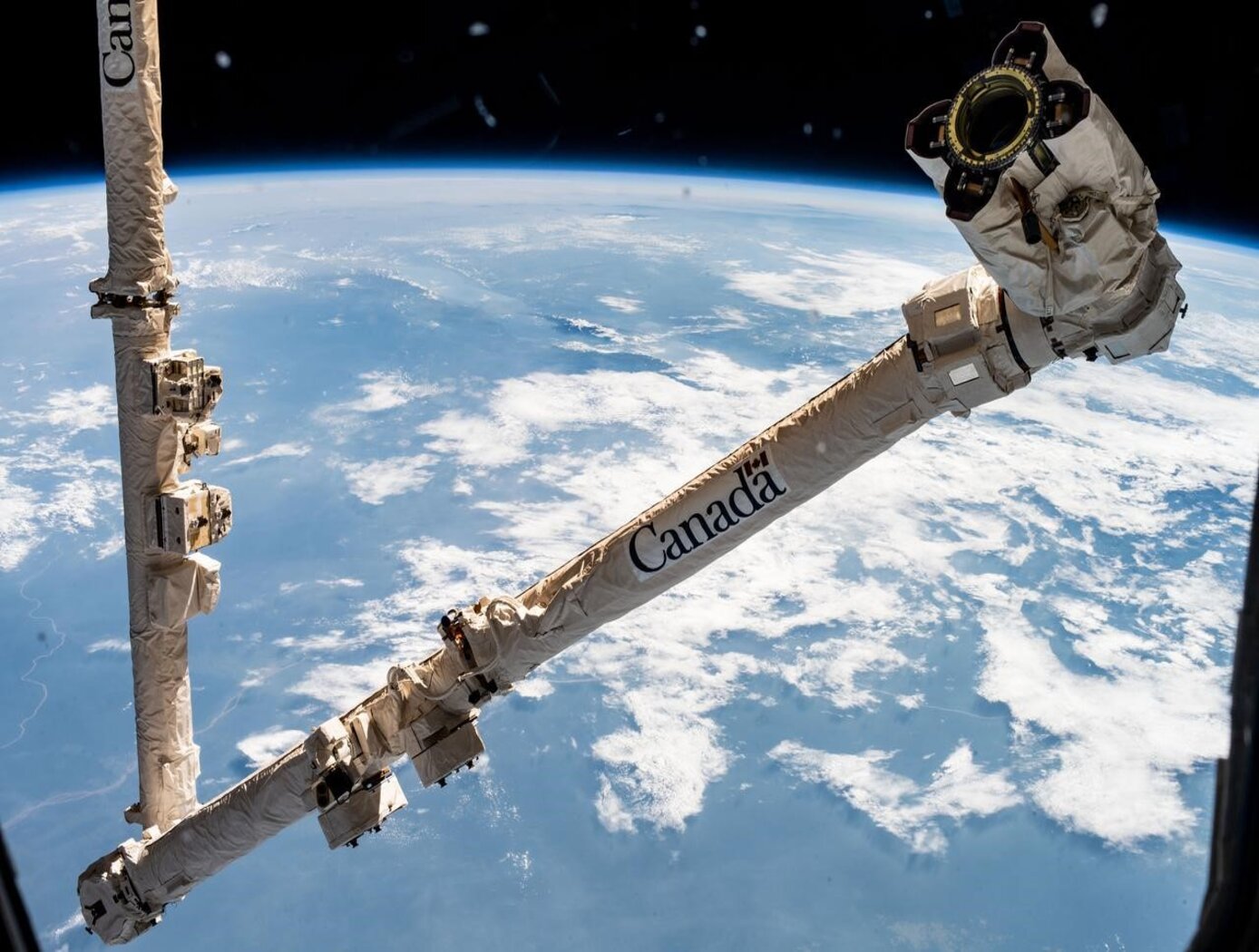
Computer Vision Lends Precision to Robotic Grappling
The goal of this computer vision software is to take the guesswork out of grapple operations aboard the ISS by providing a robotic arm operator with real-time pose estimation of the grapple fixtures relative to the robotic arm’s end effectors. To solve this Perspective-n-Point challenge, the software uses computer vision algorithms to determine alignment solutions between the position of the camera eyepoint with the position of the end effector – as the borescope camera sensors are typically located several centimeters from their respective end effector grasping mechanisms.
The software includes a machine learning component that uses a trained Region-based Convolutional Neural Network (R-CNN) to provide the capability to analyze a live camera feed to determine ISS fixture targets a robotic arm operator can interact with on orbit. This feature is intended to increase the grappling operational range of ISS’s main robotic arm from a previous maximum of 0.5 meters for certain target types, to greater than 1.5 meters, while significantly reducing computation times for grasping operations.
Industrial automation and robotics applications that rely on computer vision solutions may find value in this software’s capabilities. A wide range of emerging terrestrial robotic applications, outside of controlled environments, may also find value in the dynamic object recognition and state determination capabilities of this technology as successfully demonstrated by NASA on-orbit.
This computer vision software is at a technology readiness level (TRL) 6, (system/sub-system model or prototype demonstration in an operational environment.), and the software is now available to license. Please note that NASA does not manufacture products itself for commercial sale.

